Induction Generator Overview and Operation Modes
Induction Generator Notes
Introduction to Induction Generators
-
Definition: An induction generator is a polyphase induction machine functioning as a generator.
- Polyphase refers to systems with multiple voltages out of phase with each other (like a three-phase system).
-
Operation with AC Supply: When connected to a 3-phase AC supply, it functions as a motor.
- AC Supply: Alternating Current where the flow of electric charge periodically reverses direction.
-
Speed and Slip:
- Synchronous Speed: The speed at which the magnetic field rotates, usually faster than rotor speed.
- Slip: The difference between synchronous speed and actual rotor speed; positive in motor mode and negative in generator mode.
-
Conversion to Generator: If coupled to a prime mover, it can exceed synchronous speed, reversing slip and current direction.
- Prime Mover: A machine (like a turbine) that moves an induction motor beyond its synchronous speed.
-
Power and Torque Reversal: When operating as a generator, the electrical energy is fed back to the supply.
- Torque: A force that causes rotation; reverses in generator mode.
-
Reactive Power: Drawn from the supply to maintain magnetic fields within the machine.
- Reactive Power: Imaginary component of power, essential for magnetic field generation in AC systems.
Modes of Operation
-
Grid Connected Operation
- Direct connection to the grid; reactive power is supplied by the grid.
- Initially functions as a motor before being sped up by the prime mover to become a generator.
-
Self-Excited/Stand-Alone Operation
- Does not rely on a grid supply for reactive power; uses a capacitor bank instead.
- Capacitor Bank: A set of capacitors used to provide reactive power and stabilize voltage.
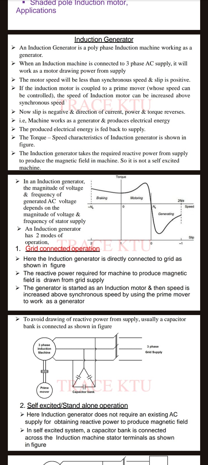
Torque-Speed Characteristics
- Characteristics Summary: Shows different operational regions such as braking, motoring, and generating.
- Braking: Region where torque is opposite to motion; used to slow down machines.
- Motoring: Region where machine takes power from the grid and performs work.
- Generating: Region where machine delivers power back to the grid.
Reactive Power Management
- Capacitor Bank Connection: Used to compensate for reactive power demand, reducing grid dependency.
flowchart TB
    A[3 Phase Induction Machine]
    B[Prime Mover]
    C[Capacitor Bank]
    D[3 Phase Grid Supply]
    A --> B
    A --> C --> D
Insights
- Induction Generators are efficient for applications where a connection to a prime mover is possible, such as wind turbines.
- Self-Excited Mode is valuable for off-grid situations as it generates its own reactive power.
- Torque-Speed Analysis helps in designing systems that can switch effectively between motor and generator modes.
Extended readings:
Split Phase and Capacitor Motors
Split Phase Motor
-
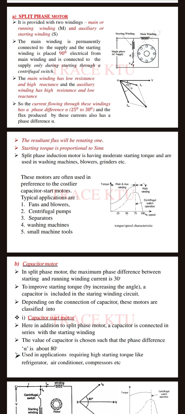
Windings:
- Main Winding (M): Connected permanently to the supply.
- Auxiliary Winding (S): Placed 90° electrical from main winding, used during starting through a centrifugal switch.
-
Characteristics:
- Main Winding: Low resistance, high reactance.
- Auxiliary Winding: High resistance, low reactance.
- Phase Difference (α): Current through the windings has a phase difference of 25° to 30°. This induces a rotating magnetic field which aids in starting torque.
-
Performance:
- The resultant flux is rotating, contributing to starting torque proportional to .
- Offers moderate starting torque, making it suitable for appliances like washing machines, blowers, and grinders.
-
Applications:
- Fans and blowers
- Centrifugal pumps
- Separators
- Washing machines
- Small machine tools
-
Advantages: Often preferred over more expensive capacitor-start motors for moderate torque requirements.
Capacitor Motor
-
Enhancement: Includes a capacitor to improve starting torque by increasing the phase difference.
-
Types:
- Capacitor Start Motor:
- Additional capacitor in series with starting winding.
- Designed to achieve a phase difference of about 80°.
- Capacitor Start Motor:
-
Applications: Suitable for high starting torque applications like refrigerators, air conditioners, and compressors.
Key Differences
| Feature | Split Phase Motor | Capacitor Motor |
|---|---|---|
| Phase Difference | 25° to 30° | Up to 80° |
| Torque | Moderate starting torque | High starting torque |
| Applications | Household appliances | Industrial and heavy-duty appliances |
Diagram: Motor Torque/Speed Characteristics
graph TDA[Main & Aux Winding] --> B[Torque]B --> C{Operation of Centrifugal Switch}C -->|Engages| D[Auxiliary Stops]D --> E[Main Winding Continues]E --> F[100% Speed]
Understanding the phase difference and its impact on starting torque is crucial for choosing the right motor based on application requirements. Different motor designs serve specific needs, balancing cost and performance.
Extended readings:
Notes on Single-Phase Induction Motors
Capacitor Start Capacitor Run Motor
Overview
- Similarity to Capacitor Start Motor: Identical with the difference that both starting and running windings remain connected throughout.
- Purpose: Provides improved starting torque and stability during operation.
Design Variations
Design 1
- Single Capacitor: Used for both starting and running.
- Benefits:
- No centrifugal switch needed.
- Improved power factor and efficiency.
Design 2
- Two Capacitors (C1 and C2) :
- C1: Smaller capacitor, permanently connected for optimized running.
- C2: Larger capacitor, used for starting, connected via a centrifugal switch.
- Constant Torque: Ensures stable operations, suitable where silence is critical (e.g., hospitals, studios).
Diagram Insights
- Torque-Speed Characteristic: Indicates torque variations with speed increase and centrifugal switch operation.
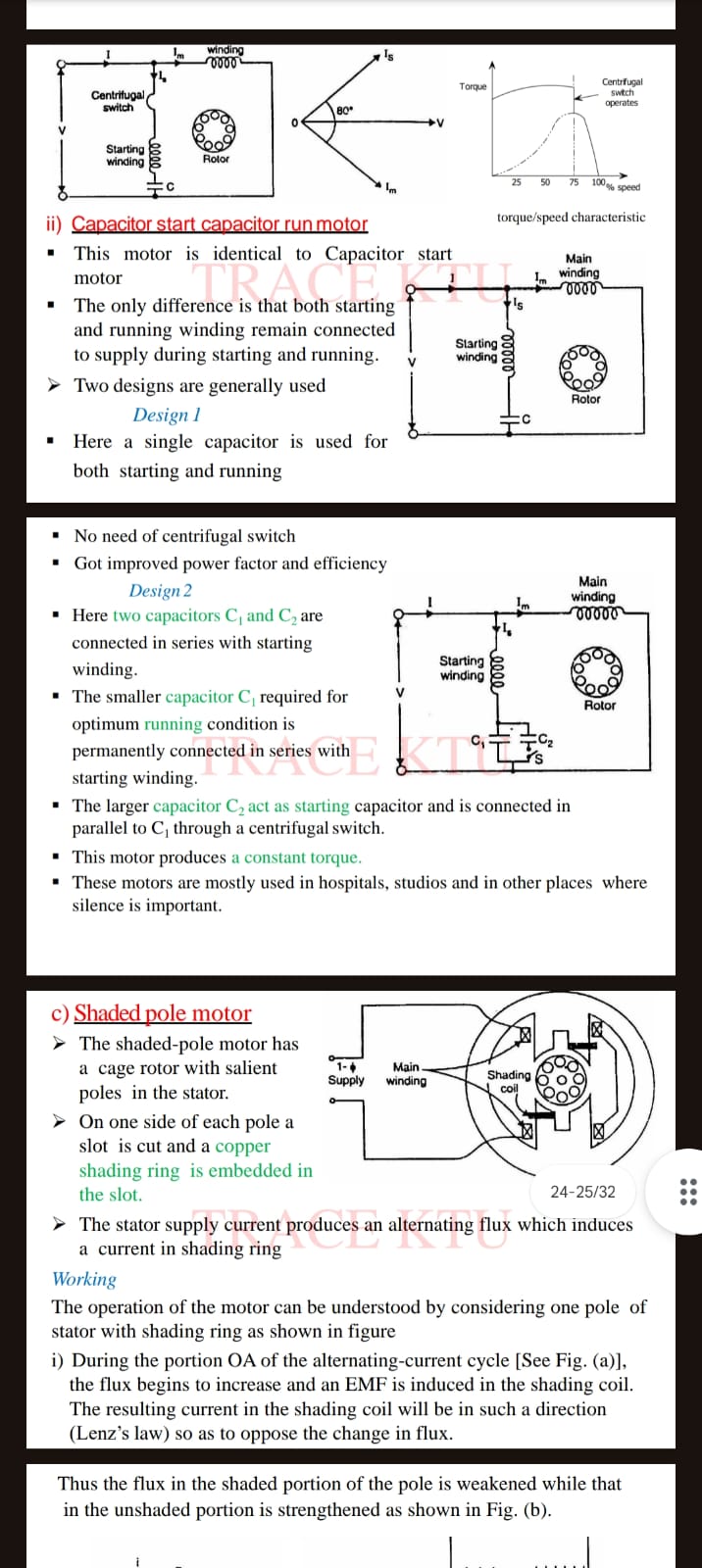
Shaded Pole Motor
Design and Functionality
- Structure:
- Cage Rotor: Features prominent poles in the stator.
- Shading Ring: Copper ring in a slot on each pole for enhancing magnetic field strength.
Working Principle
- Flux Changes:
- Alternating current induces a flux in the shading coil.
- The shading coil counteracts flux changes via Lenz’s Law, affecting shaded and unshaded portions differently.
Applications
- Common Uses: Cost-effective and simple but with low starting torque, used in small appliances like fans.
Diagram Explanation
- Illustrates the interaction of main winding with the shading ring, showing flux variations.
Additional Notes
- Efficiency Improvements: Techniques like using capacitors for better power factor and noise reduction.
- Practical Uses: Emphasizes designs favorable for environments requiring quiet, efficient operation.
Extended Learning
- Further Readings: Recommended for deeper understanding of motor design variations and applications.
Extended readings: