VLAN CHeatsheet
VLAN Configuration and Management Notes
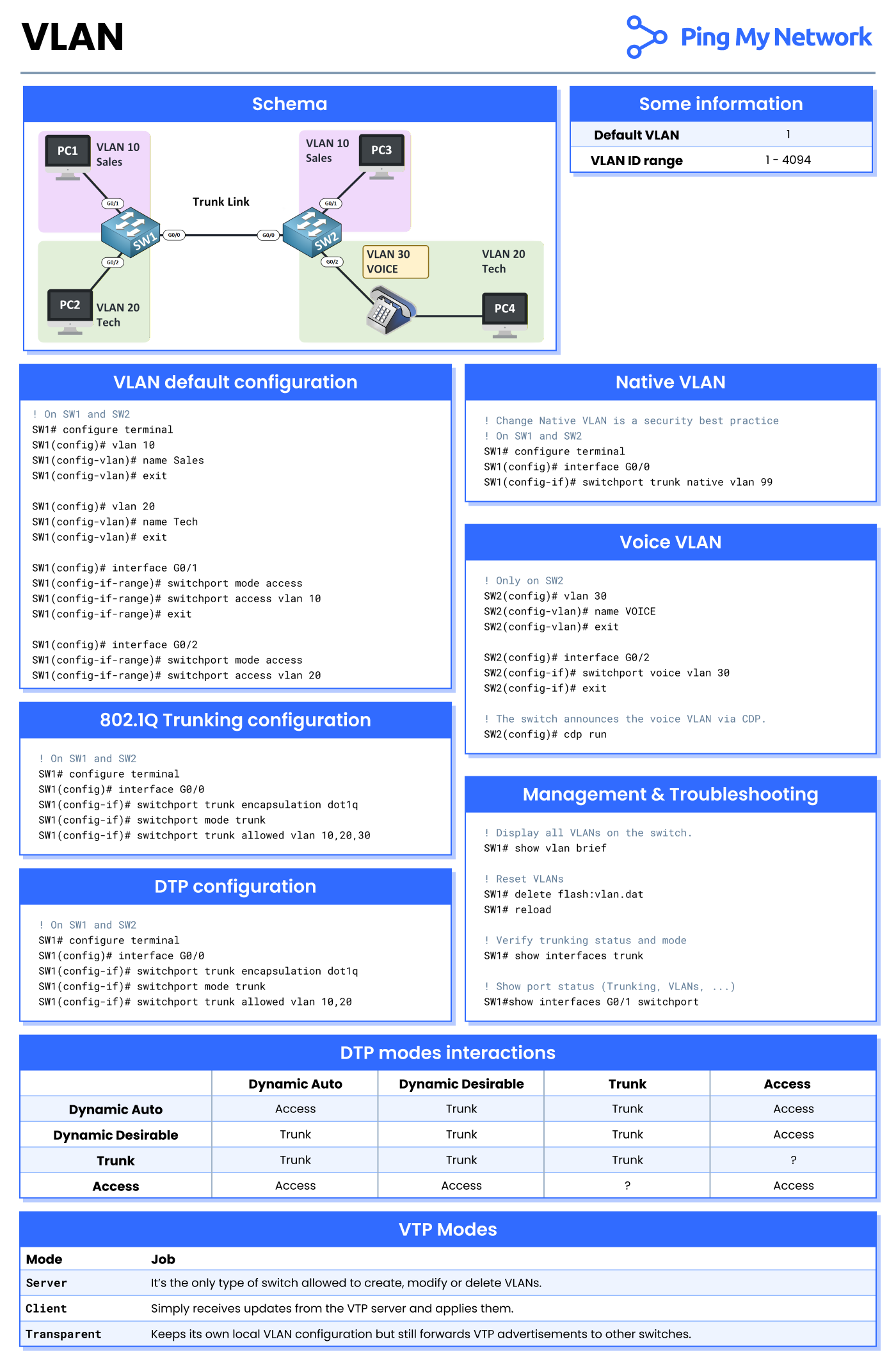
Schema
The VLAN schema involves several switches (SW1, SW2) and PCs (PC1, PC2, PC3, PC4) connected via trunk links. Each PC is assigned to a specific VLAN:
- PC1 and PC3: VLAN 10 (Sales)
- PC2 and PC4: VLAN 20 (Tech)
- VLAN 30: VOICE
This schema highlights the segregation of network traffic for security and efficiency.
Some Information
- Default VLAN: 1
- VLAN ID Range: 1-4094
The default VLAN is typically used for untagged traffic. The ID range indicates the potential number of VLANs manageable by a network device, offering extensive flexibility in segmentation.
VLAN Default Configuration
On SW1 and SW2
SW1# configure terminalSW1(config)# vlan 10SW1(config-vlan)# name SalesSW1(config-vlan)# exitSW1(config)# vlan 20SW1(config-vlan)# name TechSW1(config-vlan)# exitSW1(config)# interface G0/1SW1(config-if-range)# switchport mode accessSW1(config-if-range)# switchport access vlan 10SW1(config)# interface G0/2SW1(config-if-range)# switchport mode accessSW1(config-if-range)# switchport access vlan 20
Access mode is set for each VLAN to ensure specific PCs are placed into their respective VLANs. This configuration is key for segregating network traffic.
Native VLAN
On SW1 and SW2
SW1# configure terminalSW1(config)# interface G0/0SW1(config-if)# switchport trunk native vlan 99
Changing the native VLAN is a security best practice to prevent VLAN hopping, reducing potential threats.
Voice VLAN
Only on SW2
SW2(config)# vlan 30SW2(config-vlan)# name VOICESW2(config-vlan)# exitSW2(config)# interface G0/2SW2(config-if)# switchport voice vlan vlan 30
This configuration ensures the proper handling and prioritization of voice traffic. The switch announces the voice VLAN via CDP (Cisco Discovery Protocol).
802.1Q Trunking Configuration
On SW1 and SW2
SW1# configure terminalSW1(config)# interface G0/0SW1(config-if)# switchport trunk encapsulation dot1qSW1(config-if)# switchport mode trunkSW1(config-if)# switchport trunk allowed vlan 10,20,30
802.1Q is used to allow multiple VLANs to pass through a single trunk link. It encapsulates traffic to maintain the VLAN information across switches.
DTP Configuration
On SW1 and SW2
SW1# configure terminalSW1(config)# interface G0/0SW1(config-if)# switchport trunk encapsulation dot1qSW1(config-if)# switchport mode trunkSW1(config-if)# switchport trunk allowed vlan 10,20
Dynamic Trunking Protocol (DTP) aids in the automatic negotiation of trunking on a link. Proper DTP configuration is crucial for efficient VLAN management.
DTP Modes Interactions
| Dynamic Auto | Dynamic Desirable | Trunk | Access | |
|---|---|---|---|---|
| Dynamic Auto | Access | Trunk | Trunk | Access |
| Dynamic Desirable | Trunk | Trunk | Trunk | ? |
| Trunk | Trunk | Trunk | Trunk | ? |
| Access | Access | ? | ? | Access |
Understanding the interaction of DTP modes helps in configuring network links that adapt to different connectivity scenarios.
VTP Modes
| Mode | Job |
|---|---|
| Server | Only type of switch allowed to create, modify, or delete VLANs. |
| Client | Receives updates from the VTP server and applies them. |
| Transparent | Maintains its own VLAN configuration but forwards VTP advertisements to other switches. |
The VTP (VLAN Trunking Protocol) ensures VLAN consistency across a network, eliminating guesswork and potential misconfigurations.
Management & Troubleshooting
Display all VLANs on the switch
SW1# show vlan brief
Reset VLANs
SW1# delete flash:vlan.datSW1# reload
Verify trunking status and mode
SW1# show interfaces trunk
Show port status (Trunking, VLANs, ...)
SW1# show interfaces G0/1 switchport
Regular management and proper troubleshooting steps ensure stable and reliable VLAN operations. These commands provide insightful details about the current VLAN settings and connectivity on the switches.