**Title: Understanding Electric Vehicles and Basic Electrical Concepts**
Basic Electrical Components

Introduction to Electrical Components
- Definition: Electrical components are electronic parts that can be connected to create electronic circuits. They have specific functions and behaviors depending on their design.
- Importance: Understanding these components is crucial for anyone studying electronics or engaging in electrical engineering, as they form the basis of circuit design and functionality.
Common Electrical Components
-
Resistor
- Function: Limits current flow and divides voltages in a circuit.
- Thoughts: Essential in controlling the amount of current in various branches of a circuit, preventing damage to components that could be subjected to too high of a current.
-
Capacitor
- Function: Stores and releases electrical energy in a circuit.
- Thoughts: Helpful in smoothing out fluctuations in voltage and providing bursts of energy when needed, such as in power supplies and audio equipment.
-
Inductor
- Function: Stores energy in a magnetic field when electrical current passes through it.
- Thoughts: Used in various applications, like filtering in power supplies and tuning in radio circuits, emphasizing its role in controlling current changes over time.
-
Diode
- Function: Allows current to flow in one direction only, protecting circuits from reverse current.
- Thoughts: Fundamental in rectifying circuits (converting AC to DC), highlighting their necessity in power supply designs.
-
Transistor
- Function: Acts as a switch or amplifier in a circuit.
- Thoughts: Vital in modern electronic devices; understanding their operating principles is essential for developing complex circuits, especially in computing and signal processing.
Conclusion
- The knowledge of basic electrical components and their functionalities is crucial for building and analyzing electronic circuits. Mastery of these elements forms the foundation for advanced studies in electronics and electrical engineering.
Resistor Overview
Definition
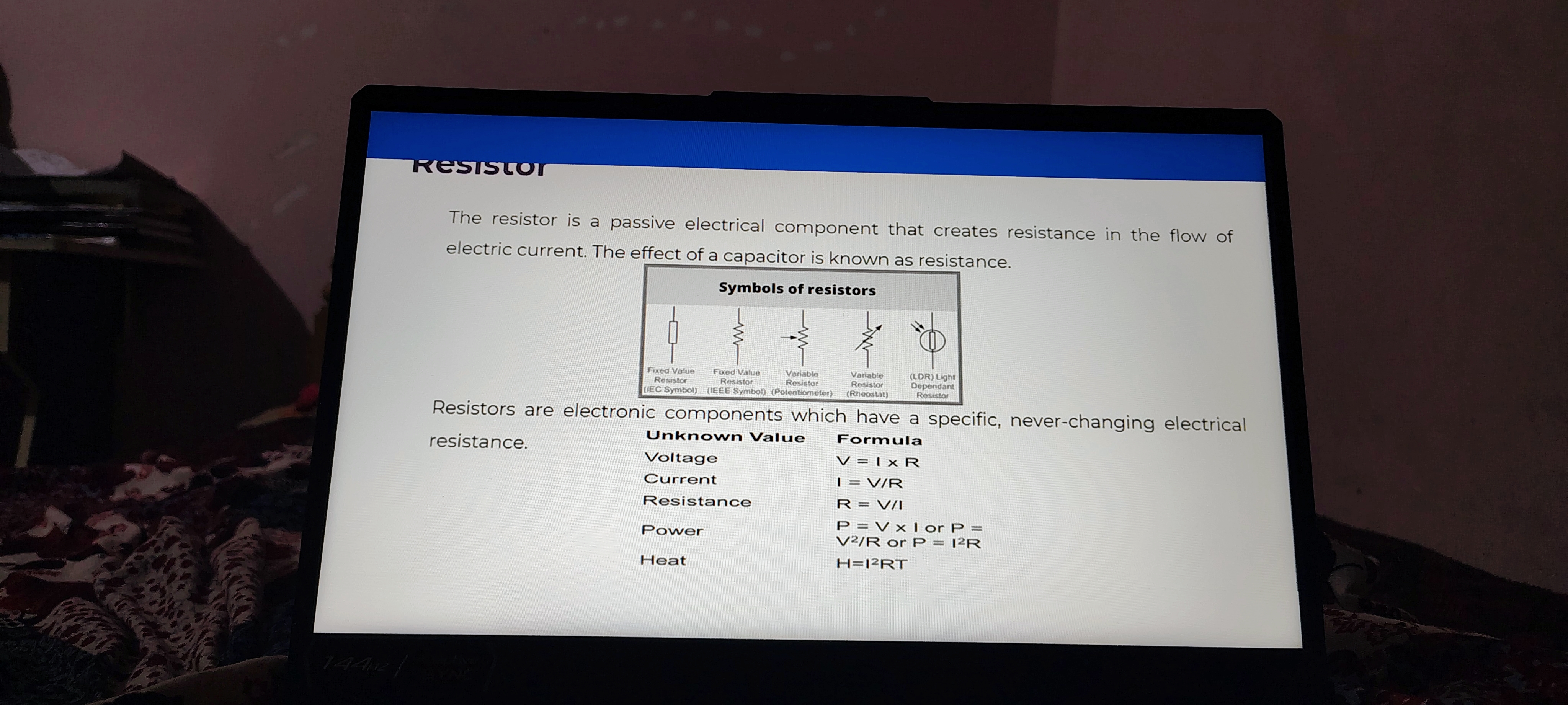
- The resistor is a passive electrical component that creates resistance in the flow of electric current.
- Thoughts: Understanding resistance is crucial for managing electrical circuits effectively. It allows for controlling current flow.
Effect of a Capacitor
- The effect of a capacitor is known as resistance.
- Additional Information: Capacitors and resistors are foundational components in electronics. While a resistor restricts current, a capacitor stores electric charge.
Symbols of Resistors
| Type | Symbol |
|---|---|
| Fixed Value Resistor (IEC) | |
| Fixed Value Resistor (IEEE) | |
| Variable Resistor (Potentiometer) | |
| Variable Resistor (Rheostat) | |
| Light Dependent Resistor (LDR) |
- Thoughts: Recognizing the symbols used for different types of resistors is essential for reading and interpreting electronic schematics.
Characteristics of Resistors
- Resistors are electronic components that have a specific, never-changing electrical resistance.
- Additional Information: Different types of resistors serve various functions, such as adjusting voltage levels or limiting current flow.
Formulas Related to Resistors
Unknown Values and Formulas
| Unknown Value | Formula |
|---|---|
| Voltage | |
| Current | |
| Resistance | |
| Power | or or |
| Heat |
- Thoughts: Mastery of these formulas can simplify problem-solving in electrical engineering and facilitates circuit analysis.
- Additional Information: These formulas are fundamental in calculating how various resistors will behave in a circuit, aiding in designing and optimizing electrical systems.
Reference:
Types of Resistor
Overview
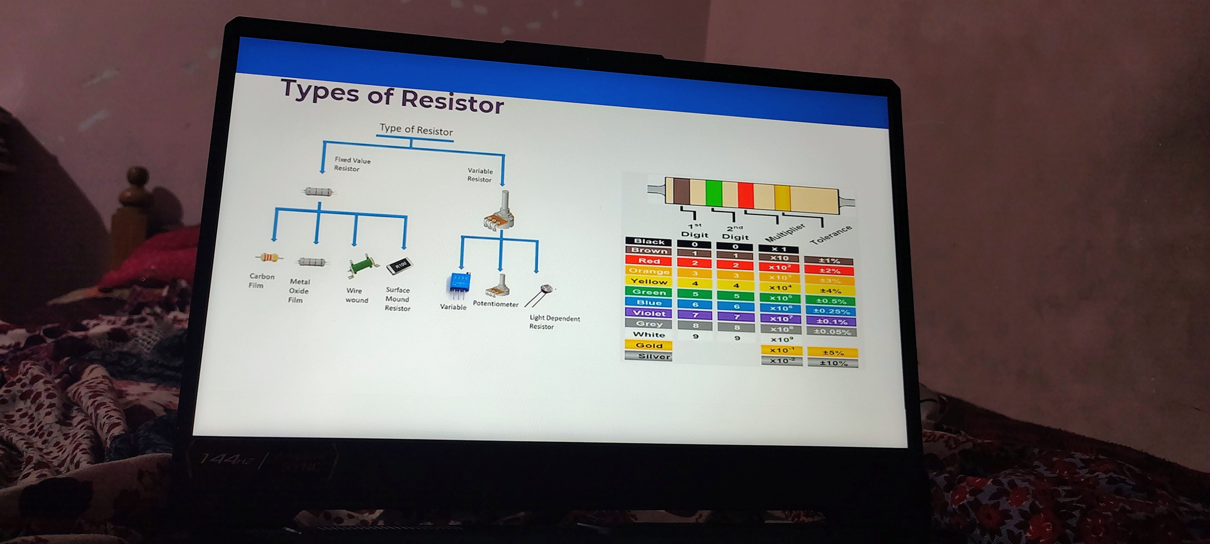
The image provides an overview of different types of resistors and their classifications. It categorizes resistors into fixed value and variable resistors, along with examples of each type. Understanding these resistors is crucial for anyone working in electronics or electrical engineering.
Fixed Value Resistors
-
Carbon Film Resistor:
- Commonly used for their stability and low cost.
- Suitable for general-purpose applications.
-
Metal Oxide Film Resistor:
- Known for higher stability and tolerance.
- Often used in applications requiring precision.
-
Wire Wound Resistor:
- Made by winding a metal wire around a core.
- Used in high power applications due to their ability to dissipate heat.
-
Surface Mount Resistor:
- Designed for mounting directly onto the surface of PCBs.
- Popular in modern electronics due to minimizing space and weight.
Variable Resistors
-
Variable Resistor:
- Allows for adjustable resistance in a circuit.
- Commonly used in applications like volume controls.
-
Potentiometer:
- A type of variable resistor with three terminals.
- Adjusts voltage output in a circuit and is widely used in audio equipment.
-
Light Dependent Resistor (LDR) :
- Resistance varies with light intensity.
- Utilized in light-sensitive applications like automatic lighting systems.
Resistor Color Code
The image also includes a resistor color code chart, which helps identify the resistance and tolerance of a resistor based on its color bands. Here’s the extracted information in table format:
| Color | 1st Digit | 2nd Digit | Multiplier | Tolerance |
|---|---|---|---|---|
| Black | 0 | 0 | x10^0 | ±1% |
| Brown | 1 | 1 | x10^1 | ±1% |
| Red | 2 | 2 | x10^2 | ±2% |
| Orange | 3 | 3 | x10^3 | ±2% |
| Yellow | 4 | 4 | x10^4 | ±5% |
| Green | 5 | 5 | x10^5 | ±0.5% |
| Blue | 6 | 6 | x10^6 | ±0.25% |
| Violet | 7 | 7 | x10^7 | ±0.1% |
| Grey | 8 | 8 | x10^8 | ±0.05% |
| White | 9 | 9 | x10^9 | ±10% |
| Gold | - | - | x10^-1 | ±5% |
| Silver | - | - | x10^-2 | ±10% |
Conclusion
These notes summarize the types of resistors and their characteristics, including how to determine their values using the color code method. This information is fundamental for practical applications in electronics, especially when designing or troubleshooting circuits.
Reference:
Capacitor Overview
Definition
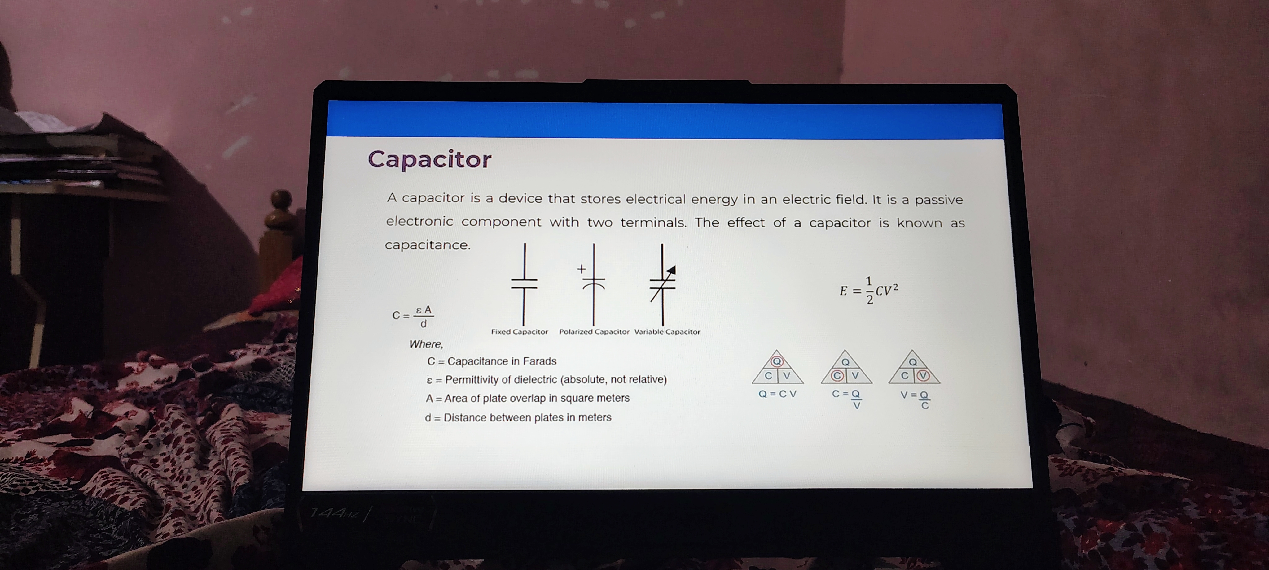
- Capacitor: A device that stores electrical energy in an electric field.
- Thoughts: Capacitors are key components in many electronic circuits, as they can release energy quickly when needed and are essential for filtering and managing power supply.
Characteristics
- Passive Electronic Component: Does not require external energy to operate independently.
- Two Terminals: The basic design allows it to be connected in various circuits.
Capacitance Formula
- Capacitance (C) :
- Where:
- : Capacitance in Farads
- : Permittivity of the dielectric (absolute, not relative)
- : Area of plate overlap in square meters
- : Distance between plates in meters
- Ideas: Understanding this formula helps in selecting capacitors for specific applications, as it describes how the physical characteristics of the capacitor affect its ability to store charge.
- Where:
Energy Stored
- Energy (E) :
- This shows how the energy stored in a capacitor is dependent on its capacitance and the voltage across it.
- Additional Information: The greater the capacitance and voltage, the more energy can be stored, which is vital in applications like power supply smoothing.
Voltage and Charge Relations
- Basic Relationships:
| Symbol | Meaning |
|---|---|
| Q | Charge (Coulombs) |
| C | Capacitance (Farads) |
| V | Voltage (Volts) |
- Thoughts: These equations illustrate how charge, capacitance, and voltage are interrelated, allowing engineers to calculate one variable when the other two are known.
Reference:
Types of Capacitors
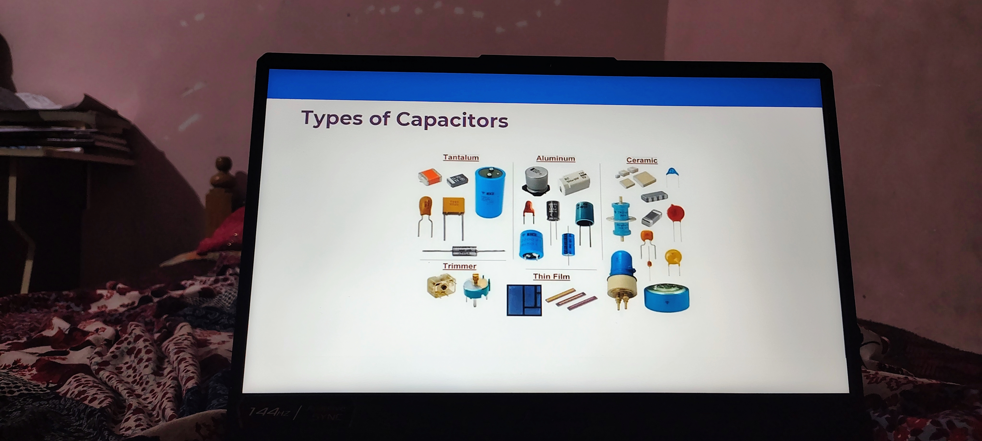
Capacitors are essential components in electronic circuits, and they come in various types, each with distinct characteristics and applications. Here are some insights based on the image:
1. Tantalum Capacitors
- Description: Tantalum capacitors are known for their high capacitance values and stability over a wide range of temperatures.
- Thoughts: These capacitors are often used in applications where size and reliability are critical, such as in mobile devices and aerospace.
- Additional Info: They have a higher cost compared to aluminum capacitors but offer better performance in many situations.
2. Aluminum Capacitors
- Description: Aluminum capacitors are widely used due to their relatively low cost and good performance.
- Thoughts: Their availability makes them a favorite for general-purpose applications, but they can be bulky compared to other types.
- Additional Info: They may have a shorter lifespan than tantalum capacitors under certain conditions, particularly at high temperatures.
3. Ceramic Capacitors
- Description: Ceramic capacitors are known for their small size and reliability, featuring a wide range of dielectric strengths.
- Thoughts: They are commonly used in high-frequency applications, like RF circuits, because of their low Equivalent Series Resistance (ESR).
- Additional Info: The capacitance value can change with applied voltage (voltage coefficient), which should be considered in design.
4. Trimmer Capacitors
- Description: Trimmer capacitors are adjustable capacitors often used for tuning applications.
- Thoughts: Their ability to be fine-tuned makes them essential in radio transmitters and receivers for precise frequency settings.
- Additional Info: They are usually less common in general electrical applications but are critical in RF applications.
5. Thin Film Capacitors
- Description: Thin film capacitors are characterized by their high precision and stability.
- Thoughts: These capacitors are used in high-performance applications where tight tolerances are required, such as in precision measurement instruments.
- Additional Info: They can be more expensive than other types due to their manufacturing process and material quality.
Summary of Capacitor Types
| Type | Characteristics | Applications |
|---|---|---|
| Tantalum | High capacitance, stable across temperatures | Mobile devices, aerospace |
| Aluminum | Low cost, good performance, larger size | General-purpose applications |
| Ceramic | Small size, reliable, good for high frequencies | RF circuits |
| Trimmer | Adjustable, used for tuning | RF transmitters/receivers |
| Thin Film | High precision, stable | Precision measurement instruments |
Understanding the various types of capacitors helps in selecting the right component for specific electronic applications, balancing factors like size, cost, and performance requirements.
Reference:
Inductor
Definition
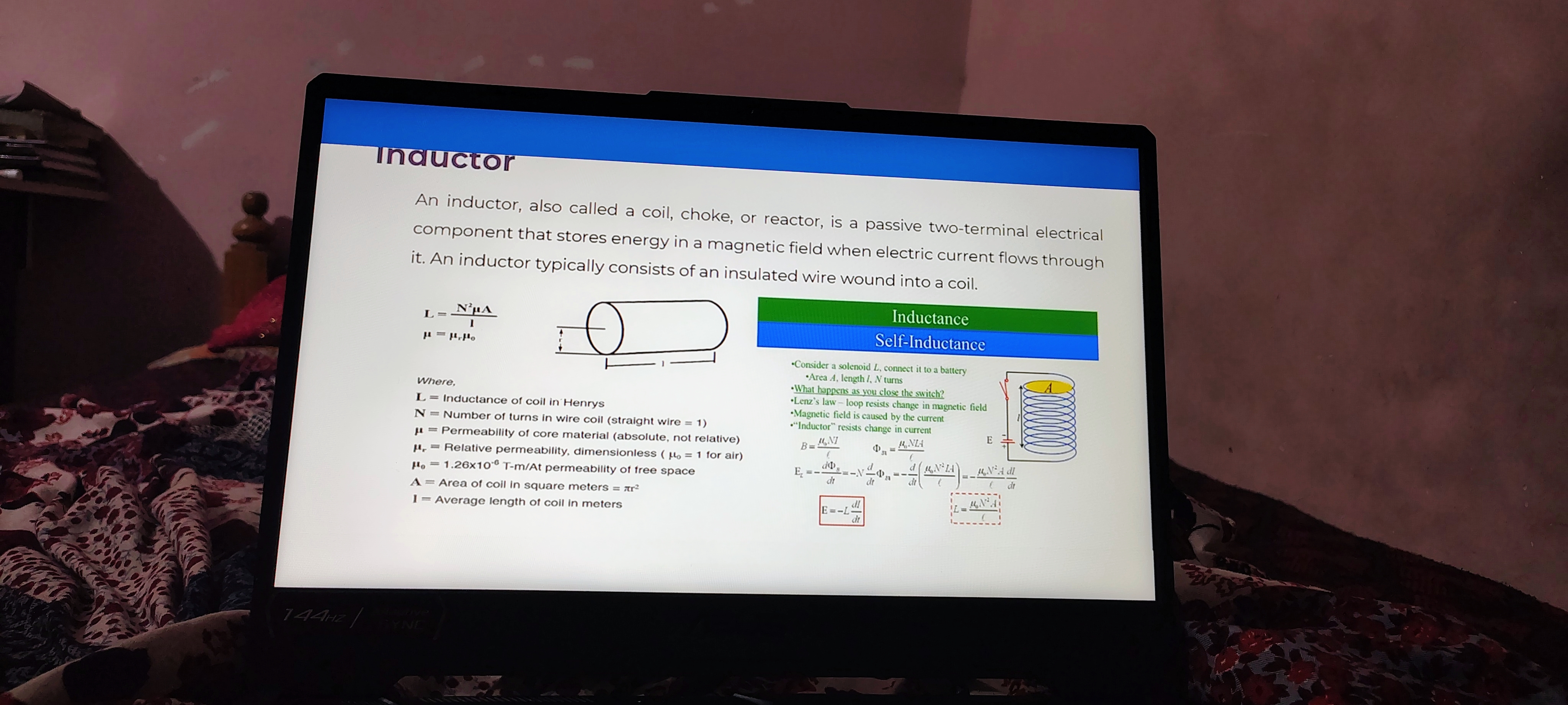
- An inductor, also known as a coil, choke, or reactor, is a two-terminal electrical component that stores energy in a magnetic field when electric current flows through it.
- Thoughts: Inductors are fundamental in controlling current in electrical circuits. Understanding their function is crucial for designing various electronic devices.
Structure
- Typically consists of an insulated wire wound into a coil.
- Idea: The physical structure of the inductor, the coil, enhances its ability to store magnetic energy. The shape and materials used can significantly affect performance.
Inductance Formula
- The inductance is given by the formula:
Where:
- = Inductance of coil in Henrys
- = Number of turns in wire coil (for a straight wire, )
- = Permeability of core material (absolute, not relative)
- = Relative permeability (dimensionless, for air)
- (permeability of free space)
- = Area of coil in square meters
- = Average length of coil in meters
- Thoughts: This formula shows that inductance increases with the number of turns and the permeability of the core material, making material selection important in inductor design.
Self-Inductance Concept
- Self-inductance refers to the property of an inductor that allows it to oppose changes in current flow through it.
- Additional Info: This property is vital in applications like transformers and energy storage devices, where maintaining a stable current is necessary.
Related Concepts
- Lenz's Law: A fundamental principle that states that an induced electromotive force (EMF) will generate a current that opposes the change in magnetic flux that produced it.
- Insight: This concept is essential for understanding how inductors react in dynamic circuits and contributes to the design of more efficient electrical systems.
Key Concepts
- Magnetic Field Relation:
- (Magnetic field strength)
- (Induced EMF)
- Thoughts: These equations further demonstrate the relationship between current, magnetic fields, and how inductors can control electrical energy flow. Understanding these relationships is crucial for anyone working with electrical circuits.
Reference:
Mutual Inductance
Key Concepts
-
Mutual Induction:
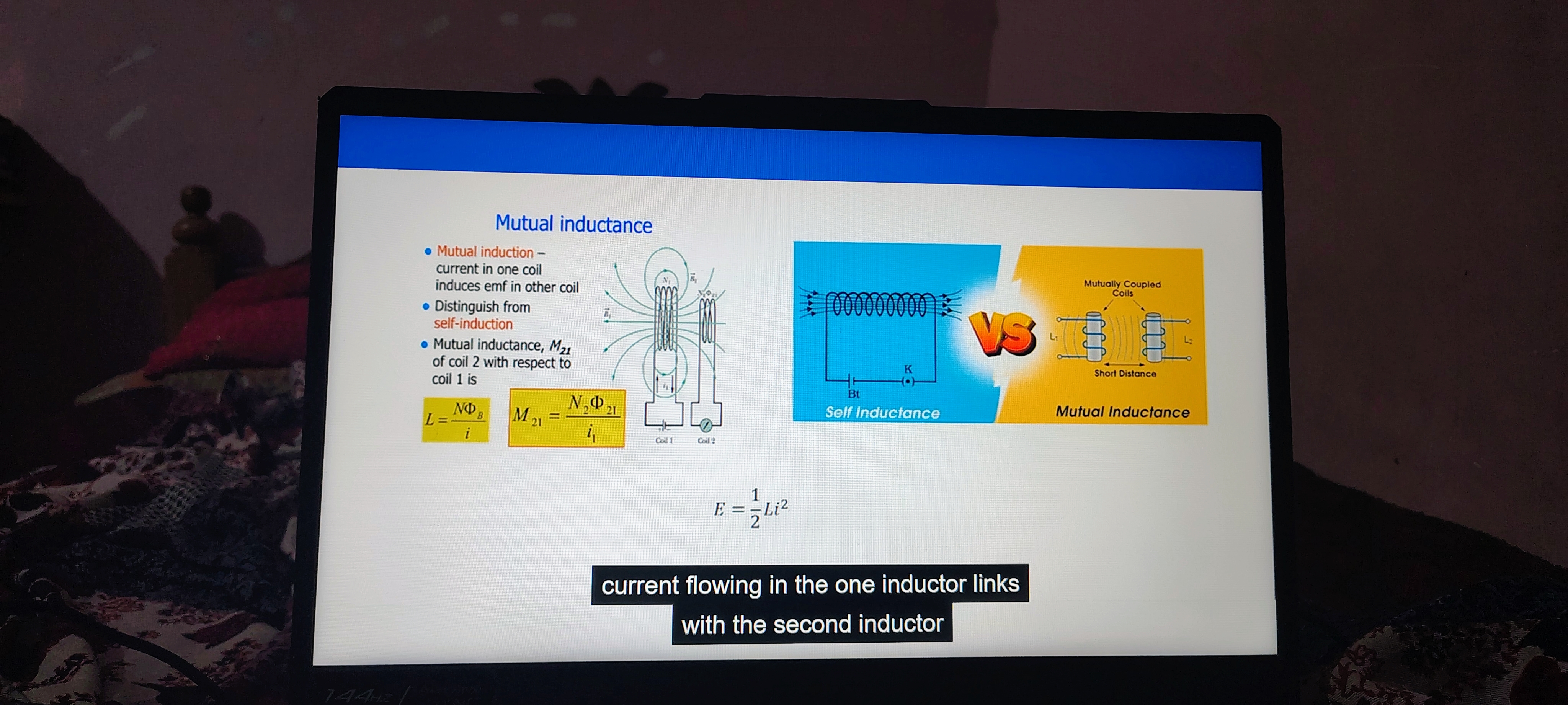
- Definition: This phenomenon occurs when the current flowing in one coil induces an electromotive force (emf) in another coil. It distinguishes from self-induction, where the induced emf is in the same coil.
- Thought: Mutual induction is essential in transformers and various electrical devices, as it allows energy transfer without direct electrical connection.
-
Distinction from Self-Induction:
- In self-induction, a single coil generates an emf due to its own changing current. In contrast, mutual induction involves two coils affecting each other through the magnetic field.
- Additional Info: While both phenomena involve inductance, their applications can vary significantly, like in inductors vs transformers.
Formulae
-
Mutual Inductance () : Where:
- = Number of turns in coil 2
- = Magnetic flux linked with coil 2 due to the current in coil 1
- = Current in coil 1
-
General Inductance Formula: Where:
- = Number of turns
- = Magnetic flux
- = Current
-
Energy Stored in Inductor:
- Explanation: This formula indicates how much energy is stored in the inductor when a current flows through it. The energy is proportional to the square of the current and the inductance.
Illustrations
- Self Inductance vs Mutual Inductance:
- Self Inductance: Represented as a single coil.
- Mutual Inductance: Shown with two coils that are closely coupled, demonstrating the interaction between them.
- Importance: Understanding these concepts is crucial for designing circuits and devices that utilize inductors efficiently.
Summary
Mutual inductance is a critical concept in electromagnetism that allows for energy transfer between coils via magnetic fields. Understanding its principles helps in grasping how transformers and inductive coupling work in electronic devices.
Reference:
Resistor vs Capacitor vs Inductor
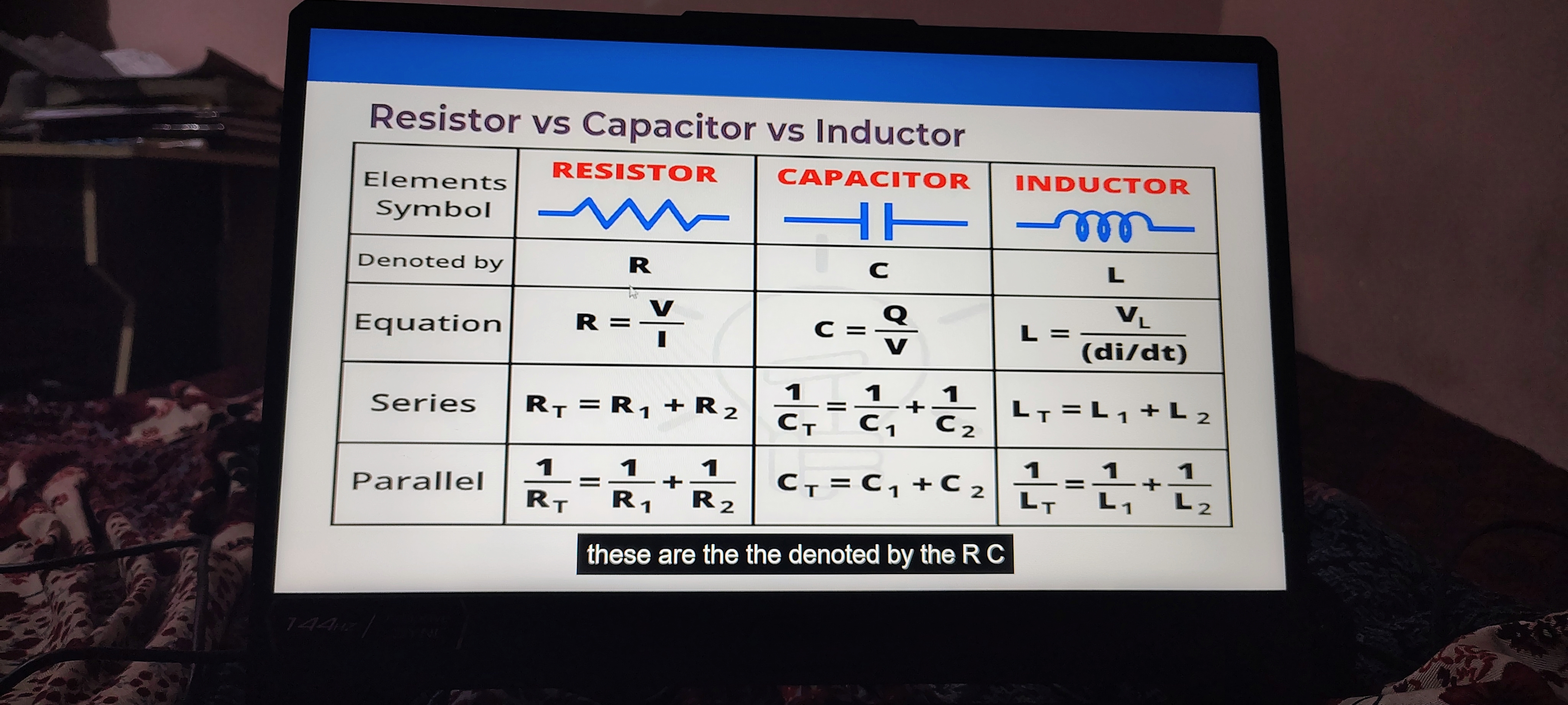
This document compares resistors, capacitors, and inductors, which are fundamental components in electrical circuits.
| Elements | Resistor | Capacitor | Inductor |
|---|---|---|---|
| Symbol | R | C | L |
| Denoted by | R | C | L |
| Equation | |||
| Series | |||
| Parallel |
Notes:
-
Resistor:
- Function: Resistors limit current flow and voltage in a circuit. They convert electrical energy into heat, which is why they get warm.
- Application: Used to control the current in various circuits, such as voltage dividers and pull-up resistors.
-
Capacitor:
- Function: Capacitors store and release electrical energy. They can smooth out fluctuations in voltage.
- Application: Commonly used in filtering applications (e.g., smoothing power supply outputs) and tuning circuits (e.g., radio frequency circuits).
-
Inductor:
- Function: Inductors store energy in a magnetic field when electrical current flows through them. They resist changes in current.
- Application: Used in filters, transformers, and energy storage in power supplies, often in conjunction with capacitors to create oscillatory circuits.
Summary of Equations:
- Ohm's Law for Resistors: This defines the relationship between voltage, current, and resistance.
- Capacitance Relationship: Describes how the capacitance value changes when capacitors are arranged in series or parallel.
- Inductance Relationship: Similar to capacitance, the inductance changes depending on how inductors are configured in the circuit.
Understanding these components and their equations is essential for designing and troubleshooting electrical and electronic systems.
Reference:
Notes on Electrical Inductance Quiz

Key Concepts
- Unit of Inductance: Henry (H)
- The basic unit of inductance in the International System of Units (SI) is Henry, symbolized as 'H'.
- Inductance is crucial in electrical circuits, as it relates to how the circuit responds to changes in current.
Explanation of Henry:
- Definition:
- The Henry is defined as the inductance that causes a potential difference of 1 Volt to be produced when the current through the inductor changes at a rate of 1 Ampere per second.
- This definition underscores the relationship between voltage, current, and time in magnetic fields and inductors.
Quiz Content:
- Question: What is the unit of inductance?
- Options:
- A. Henry
- B. Volt-second/A
- C. Wb/A
- D. All of these
- Correct Answer: D. All of these
- Thoughts: This highlights that various expressions can describe the same physical quantity, emphasizing the interconnectedness of electrical units. Understanding these different terms can aid in clearer communication in electrical engineering.
- Options:
Additional Information:
- Inductance in Circuits:
- Inductance is a fundamental property for components like inductors in circuits, used in filters, transformers, and energy storage elements.
- Applications:
- Knowledge of inductance is essential for designing circuits that control currents, such as in power supplies, radios, and more advanced electronic devices.
Summary:
Understanding the unit of inductance and its applications is critical for anyone studying electrical engineering or involved in designing electrical circuits. The quiz format encourages active recall, aiding comprehension of foundational concepts in electronics.
Reference:
Kirchhoff's Laws
Kirchhoff's Laws Overview
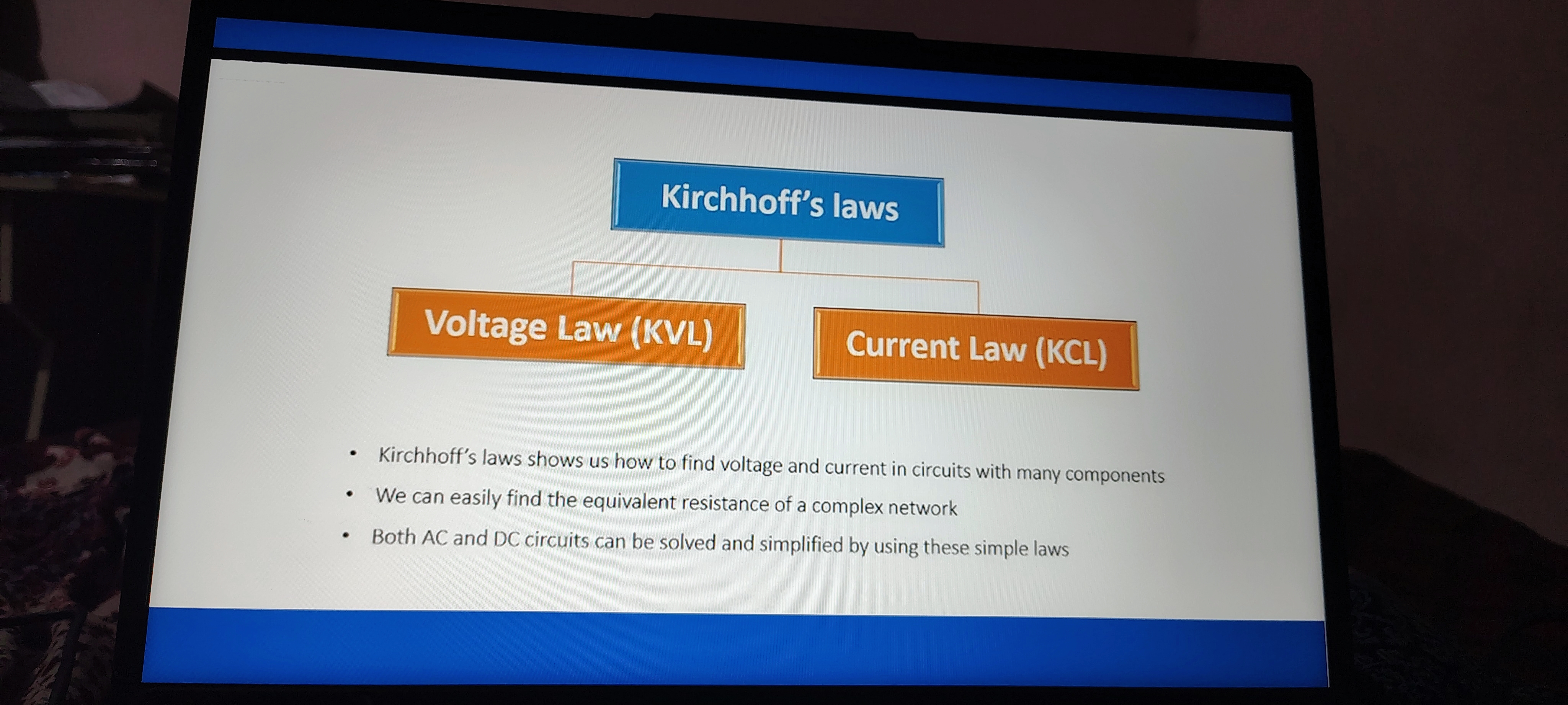
- Definition: Kirchhoff's laws are fundamental principles in electrical engineering that help analyze complex electric circuits.
- Components: These laws are divided into two main categories:
- Voltage Law (KVL) : This law states that the total voltage around any closed loop in a circuit is equal to zero. It emphasizes the conservation of energy within circuits, ensuring that all voltages rise and drop in a loop balance out.
- Current Law (KCL) : According to this law, the total current entering a junction must equal the total current leaving that junction. This reflects the conservation of charge in electrical circuits.
Key Points
- Application: Kirchhoff's laws are used to find voltage and current in circuits that contain multiple components. They are essential for both AC (Alternating Current) and DC (Direct Current) circuit analysis.
- Equivalent Resistance: Using Kirchhoff's laws, engineers can simplify the process of finding the equivalent resistance of complex networks. This is crucial for efficiently designing circuits.
- Simplification of Circuits: Both AC and DC circuits can be simplified through the application of these laws, making analysis more manageable.
By understanding these laws, one can effectively troubleshoot and design electrical circuits, ensuring they operate efficiently and safely.
Reference:
Circuit Definitions
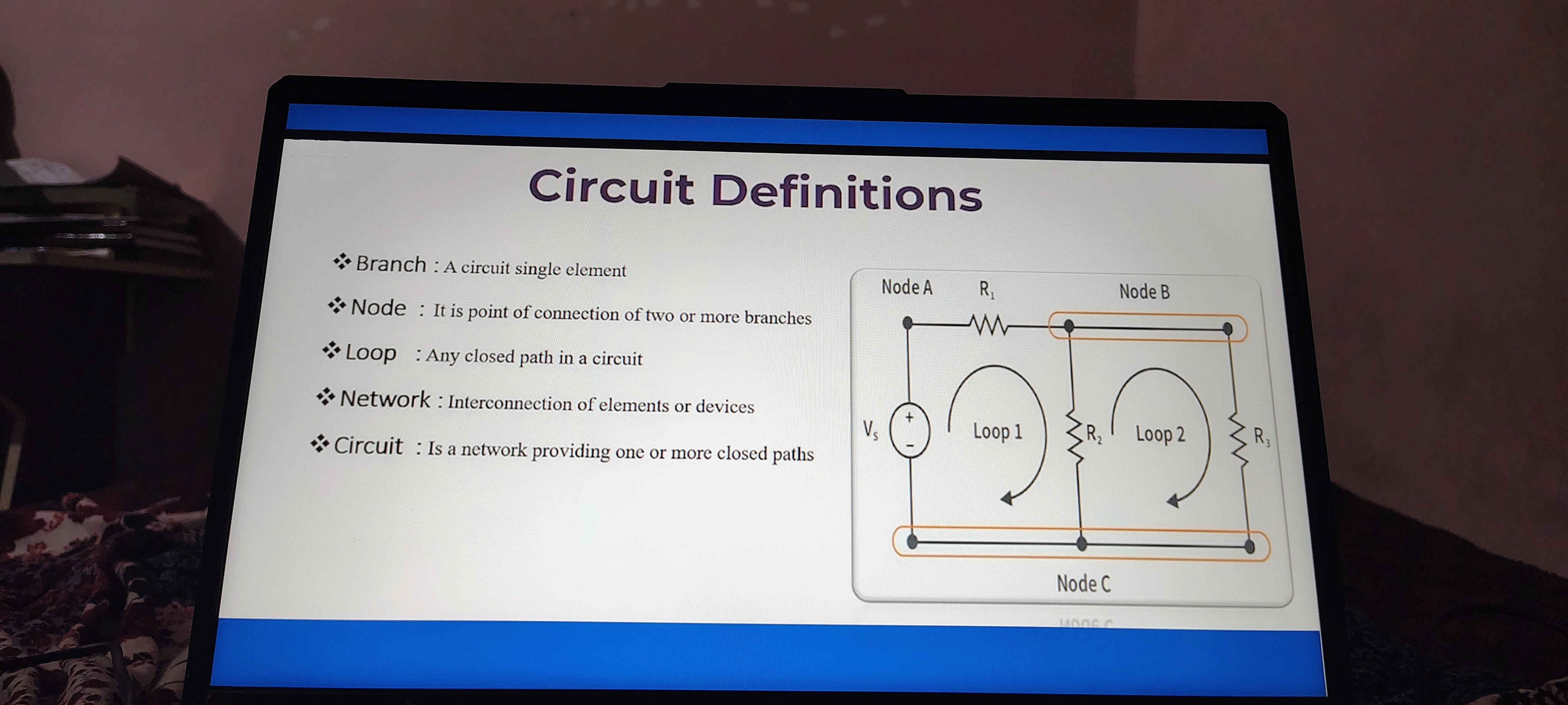
Key Terms
| Term | Definition |
|---|---|
| Branch | A circuit single element |
| Node | It is a point of connection for two or more branches |
| Loop | Any closed path in a circuit |
| Network | Interconnection of elements or devices |
| Circuit | A network providing one or more closed paths |
Notes and Additional Information
-
Branch:
- Each branch in an electrical circuit typically contains a component, such as resistors, capacitors, or inductors. Understanding branches is essential for analyzing how current flows through a circuit and how voltage is distributed.
-
Node:
- Nodes serve as junction points where two or more branches meet. Knowing how many branches connect at a node helps in applying Kirchhoff's laws, which are fundamental for circuit analysis.
-
Loop:
- A loop is formed when you can traverse a complete path in a circuit without lifting your pencil from the paper and returning to the starting point. Analyzing loops is vital for calculating currents and voltages in complex circuits using techniques like mesh analysis.
-
Network:
- A network refers to the overall configuration of elements within the circuit, including connections, branches, and nodes. The concept of networks is vital in systems like communications and power distribution.
-
Circuit:
- This term encompasses the whole system defined by its nodes, branches, and loops. Understanding circuits as networks with closed paths is crucial for designing and troubleshooting electronic systems, as well as for implementing various circuit theorems.
Diagram Insights
- The diagram in the image visualizes a basic circuit with nodes labeled A, B, and C, along with resistors and loops. This visual representation aids in illustrating how branches and loops function within a network, emphasizing the practical aspect of circuit theory.
Reference:
Kirchhoff’s Current Law (KCL)
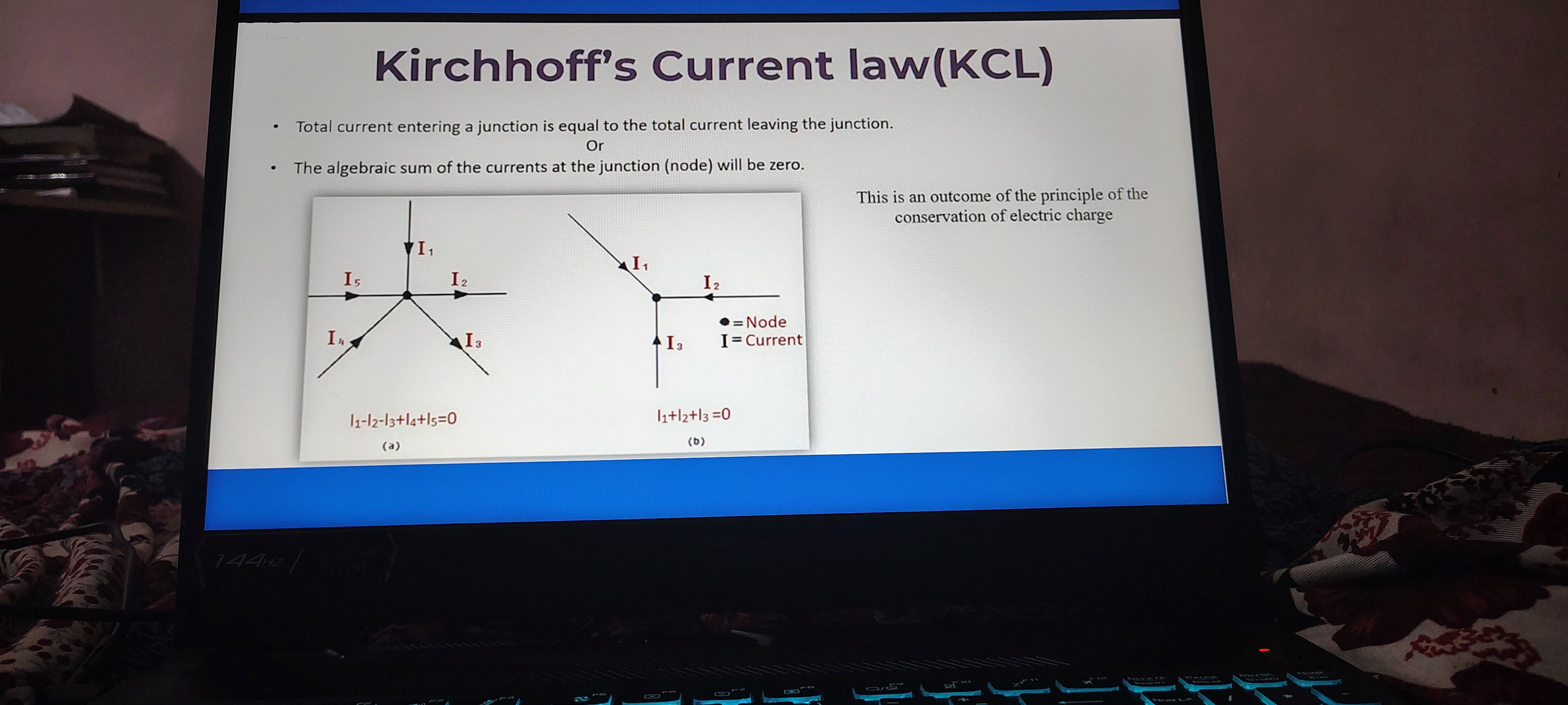
-
Total Current at a Junction: The total current entering a junction is equal to the total current leaving the junction.
- Thought: This principle is crucial in circuit analysis since it helps to maintain the balance of electrical charge. Understanding how current behaves at junctions allows engineers to design more efficient circuits.
-
Algebraic Sum of Currents: The algebraic sum of the currents at the junction (node) will be zero.
- Additional Information: If we label incoming currents as positive and outgoing currents as negative, this principle can be expressed mathematically as: where currents entering the node are considered positive and those leaving it are negative.
-
Example Equations:
- From the first diagram:
- From the second diagram:
- Thought: These equations exemplify how KCL is applied in circuit analysis. They can help in determining the unknown currents when some values are known.
-
Conservation of Electric Charge: KCL stems from the principle of conservation of electric charge.
- Additional Information: This means that charge cannot be created or destroyed in an isolated system; it can only flow from one part of the circuit to another. This fundamental concept underlies all electrical engineering and physics.
Visual Representation:
- Diagrams provided illustrate currents () at various junctions and how they interact according to KCL principles.
Reference: